Sabtu, 08 Januari 2011

Lab 4.3.4.3 Configuring a LAN with Discontiguous Subnets

Langkah 1: Hubungkan peralatan

  1. Hubungkan Router1 interface Serial 0/0/0 untuk antarmuka Router2 Serial 0/0/0 menggunakan kabel serial
  2. Hubungkan Router2 interface Serial 0/0/1 untuk antarmuka Router3 Serial 0/0/1 menggunakan kabel serial.
  3. Hubungkan Router1 untuk Router3 dengan kabel serial seperti ditunjukkan dalam diagram dan tabel.
  4. Hubungkan Fa0 di / 0 interface setiap router ke Fa0 / 1 antarmuka pada saklar yang sesuai.
  5. Hubungkan PC dengan kabel konsol untuk melakukan konfigurasi pada router dan switch.
  6. Hubungkan masing-masing PC host untuk Fa0 pada / 2 antarmuka pada saklar dengan menggunakan suatu lurus-melalui kabel.
Langkah 2: Lakukan konfigurasi dasar pada Router1
Lakukan konfigurasi dasar tentang Router1 dengan nama host, interface, konsol, Telnet, dan diistimewakan password sesuai dengan diagram tabel. Gunakan RIP sebagai protokol routing, dan mengiklankan terlampir jaringan. Simpan konfigurasi.
Langkah 3: Konfigurasi router lainnya
Lakukan konfigurasi dasar yang sama pada Router2 dan Router3 dengan nama host, interface, konsol, Telnet, dan password istimewa sesuai dengan diagram tabel. Gunakan RIP sebagai protokol routing, dan mengiklankan terpasang jaringan. Simpan konfigurasi.
Langkah 4: Konfigurasi host dengan alamat IP yang tepat, subnet mask, dan gateway default
Mengkonfigurasi setiap host dengan alamat IP yang tepat, subnet mask, dan gateway default.
Dari konfigurasi yang diberikan, apa yang akan menjadi alamat IP subnetwork berikutnya tersedia di 172.30.0.0 jaringan?
Jawaban : 172.30.3.0
Jika Anda diperlukan untuk mengakomodasi LAN tambahan dengan 60 host, apa masker yang akan Anda gunakan untuk itu subnetwork?
Jawaban : / 26 (atau 255.255.255.192)
Langkah 5: Pastikan bahwa jaringan berfungsi
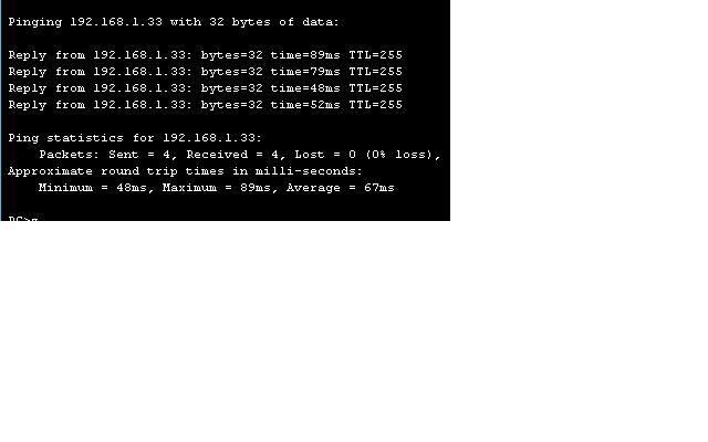
a. Dari setiap host, ping gateway default.
Apakah ping dari Host1 berhasil? Ya
Apakah ping dari host2 berhasil? Ya
Apakah ping dari sukses Host3? Ya
Jika jawabannya tidak untuk pertanyaan, memecahkan masalah konfigurasi router dan host
untuk menemukan kesalahan. Ping lagi sampai mereka berhasil.
b. Untuk setiap router, melihat status interface. Utama # show interface ip singkat
Branch1 # show ip interface singkat
Branch2 # show ip interface singkat
Apakah status dan protokol terdaftar sebagai up untuk semua interface yang aktif?
Jawaban : Ya.
Jika jawabannya tidak, memecahkan masalah konfigurasi router untuk menemukan kesalahan. Periksa kembali sampai status dan protokol yang up.
Langkah 6: Memeriksa tabel routing
Dari topologi jaringan, berapa banyak jalan harus setiap laporan router dalam tabel routing untuk memiliki lengkap gambar jaringan?
Jawaban : 6 Pada setiap router, melihat tabel routing. Perintah dan output untuk Main ditunjukkan berikut ini:
Masalah apa yang Anda lihat dalam tabel routing?
Jawaban : Setiap router hanya melaporkan dua jaringan terhubung langsung dan rute ringkasan untuk satu RIP tidak berhubungan rute. Rute subnet yang hilang.
Langkah 7: Identifikasi dan berusaha untuk memperbaiki masalah
  1. Dari konfigurasi router, mengidentifikasi alasan untuk masalah yang Anda temukan pada Langkah 6. Jawaban : Router menggunakan RIP saat turut berpartisipasi dalam jaringan yg tdk berhubungan tanpa menentukan versi 2. RIP versi 1 adalah classful dan tidak melaporkan informasi subnet.
  2. Pada setiap router, menjalankan perintah untuk memperbaiki masalah ini. Perintah sampel dan keluaran untuk Utama ditampilkan.
  3. Kembali memeriksa tabel routing dengan hati-hati. Jelaskan mengapa, meskipun setiap router sekarang memiliki rute RIP, masih ada masalah dengan tabel. informasi subnet khusus masih hilang. Apa yang harus dilakukan untuk memperbaiki masalah? Matikan auto-summarization.
  4. Pada semua tiga router, berikan perintah untuk memperbaiki masalah ini. Contoh untuk Main ditampilkan. Utama (config-router) # no auto-summary
Langkah 8: Pastikan bahwa masalah tersebut telah dikoreksi
Lihat tabel routing. Rute harus dilaporkan sebagai ditampilkan untuk router utama.
Langkah 9: Refleksi
a. Kapan itu penting untuk melihat semua rute yang mungkin dalam tabel routing?
Jawaban : selama pemecahan masalah, atau ketika menangkap sepenuhnya berfungsi jaringan sebagai dasar.
RIP versi 2 mendukung VLSM, tapi berubah ke versi 2 tidak sepenuhnya menyelesaikan masalah. Mengapa? Jawaban: Apakah versi 1 atau versi 2, RIP masih merupakan protokol distance vector, dan protokol distance vector default ke summarization otomatis.

Lab 4.3.3.3 Calculating Route Summarization

Langkah 1: Lengkapi tabel summarization untuk RouterC
RouterC Network
Network Number in Binary
Network Number in Decimal
Fa0/0
11000000.10101000.00000001.01000000
192.168.1.64
Fa0/1
11000000.10101000.00000001.01100000
192.168.1.96
Summary Route
11000000.10101000.00000001.01000000
192.168.1.64/26
Langkah 2: Lengkapi tabel summarization untuk RouterB
RouterB Network
Network Number in Binary
Network Number in Decimal
Fa0/0
11000000.10101000.00000001.00100000
192.168.1.32
Fa0/1
NA
NA
Summary Route
111000000.10101000.00000001.00100000
192.168.1.32/27
Langkah 3: Lengkapi tabel summarization untuk RouterA
RouterA
Network Number in Binary
Network Number in Decimal
Fa0/0
11000000.10101000.00000001.10000000
192.168.1.128
Fa0/1
NA
NA
Serial 0/0/0
11000000.10101000.00000001.00000100
192.168.1.4
Serial 0/0/1
11000000.10101000.00000001.00001000
192.168.1.8
Summary Route from RouterC
11000000.10101000.00000001.01000000
192.168.1.64
Summary Route
from RouterB
11000000.10101000.00000001.00100000
192.168.1.32
Summary Route
11000000.10101000.00000001.00000000
192.68.1.0/24

Lab 4.2.5.5 Calculating a VLSM Addressing Scheme

Langkah 1: Memeriksa persyaratan jaringan
Gunakan diagram topologi untuk menentukan jawaban atas pertanyaan di bawah ini. Ingat bahwa alamat IP akan  diperlukan untuk setiap LAN dan WAN interface.
  1. Berapa banyak subnet yang dibutuhkan? Jawaban: 7
  2. Berapa jumlah maksimum alamat IP yang dibutuhkan untuk satu subnet tunggal? Jawaban: 55
  3. Berapa banyak host alamat IP yang dibutuhkan untuk LAN terbesar? Jawaban: 26
  4. Berapa banyak host alamat IP yang diperlukan untuk LAN berikutnya terbesar?Jawaban: 20
  5. Berapa banyak host alamat IP yang dibutuhkan untuk LAN terkecil? Jawaban: 12
  6. Berapa banyak host alamat IP yang dibutuhkan untuk setiap link WAN? Jawaban: 2 masing masing, dengan total 6
  7. Berapa jumlah total alamat IP host yang diperlukan untuk jaringan ini? Jawaban: 119
  8. Berapa jumlah total alamat IP host yang tersedia dalam jaringan 192.168.1.0/24?Jawaban:  254
  9. Jika jaringan adalah subnetted untuk memberikan 7 subnet digunakan, bisa mengatasi persyaratan yang harus dipenuhi?  Jawaban : No Subnetting untuk / 27 (dengan subnet IP nol tersedia) atau / 28 mask (tanpa IP subnet nol) akan  tidak memungkinkan untuk jumlah host per subnet yang dibutuhkan.
Langkah 2: Desain sebuah skema pengalamatan IP agar sesuai dengan kebutuhan jaringan
  1. Tentukan informasi subnet untuk subnet terbesar diperlukan.  Apa subnet ukuran terkecil yang dapat digunakan untuk memenuhi persyaratan ini? Jawaban : 64. Akankah subnet ukuran ini memungkinkan untuk pertumbuhan masa depan 10 – 15%? Jawaban : Ya. Hampir memungkinkan untuk  20%.
  2. Mengisi tabel di bawah ini dengan informasi yang sesuai. Tetapkan subnet yang tersedia pertama di  192.168.1.0 jaringan untuk LAN ini.
Langkah 3: Menentukan subnet ke link WAN antara router
  1. Mulailah dengan subnet yang tersedia berikutnya. Lengkapi tabel di bawah ini dengan informasi pengalamatan.
Langkah 4: Tetapkan IP konfigurasi untuk interface router
  1. Lengkapi tabel di bawah ini dengan tugas IP untuk interface router. Gunakan alamat host pertama IP yang tersedia untuk  router LAN interface.
Langkah 5: Tetapkan IP konfigurasi untuk workstation
Salah satu workstation telah disediakan untuk mewakili masing-masing LAN. Lengkapi tabel di bawah ini dengan IP konfigurasi  informasi untuk setiap workstation representatif.
Langkah 6: Refleksi
  1. Apakah host alamat IP terakhir yang akan digunakan oleh skema VLSM? Jawaban :  192.168.1.150
  2. LAN Anda terbesar dapat menampung pertumbuhan 15% dengan skema VLSM Anda. Manakah dari LAN lain  juga dapat mencapai tujuan ini?  Jawaban : Hanya LAN_D, meskipun LAN_C dekat.
  3. Jika Anda memutuskan untuk mengubah topeng pada mereka LAN yang tidak memenuhi tujuan 15% pertumbuhan, akan Anda  memiliki cukup alamat untuk menyelesaikan skema Anda? Jawaban : Ya.
  4. Apa yang akan alamat jaringan baru bagi empat LAN?
LAN_A: (55 * 1.15 = 63) – 192.168.1.0/25
LAN_D: (20 * 1.15 = 23) – 192.168.1.160/27
LAN_C: (26 * 1.15 = 30) – 192.168.1.128/27
LAN_B: (12 * 1.15 = 14) – 192.168.1.192/28
e.     Jika Anda ingin menyediakan link cadangan WAN redundant antara router Anda, berapa banyak subnet  akan Anda butuhkan?Jawaban: 3
  1. Bisakah Anda melakukannya dengan skema ini VLSM? Jawaban: Ya
Ringkaskan keuntungan menggunakan VLSM untuk skema pengalamatan jaringan:  Jawaban : harus mencakup kemampuan untuk skala jaringan, tambahkan subnet diperlukan, dan menambah fleksibilitas untuk desain jaringan dengan mampu desain untuk memenuhi kebutuhan pengguna tertentu.

Lab 4.2.3.2 Designing and Applying an IP Addressing Scheme

Step 1: Cable the network
  1. Connect Host1 to Switch1 port Fa0/2, using a straight-through Ethernet cable.
  2. Connect Host2 to Switch2 port Fa0/2, using a straight-through Ethernet cable.
  3. Connect Switch1 port Fa0/1 to Router1 port Fa0/0, using a straight-through Ethernet cable.
  4. Connect Switch2 port Fa0/1 to Router1 port Fa0/1, using a straight-through Ethernet cable.
Step 2: Configure the router
  1. Establish a terminal emulation session from either host to Router1.
  2. Configure the router hostname, passwords, interface IP addresses, and subnet mask. Also configure RIP as the routing protocol.
  3. Save the configuration.
Step 3: Configure the switches
  1. Establish a terminal emulation session to Switch1 from Host1.
  2. Configure the switch hostname, passwords, interface VLAN 1 IP address, subnet mask, and default gateway on Switch1.
  3. Save the configuration.
  4. Establish a terminal emulation session to Switch2 from Host2.
  5. Configure the switch hostname, passwords, interface VLAN 1 IP address, subnet mask, and default
  6. gateway on Switch2.
  7. Save the configuration.
Step 4: Configure the hosts
  1. Configure Host1 using the IP address, subnet mask, and default gateway from the table.
  2. Configure Host2 using the IP address, subnet mask, and default gateway from the table.
Step 5: Verify connectivity
To verify that the network is set up successfully, ping from Host 1 to Host 2.
Was the ping successful?
Jawaban: Ya, saya sukses membuat jaringannya di pakettracet.
If the ping is not successful, verify the connections and configurations again. Check to ensure that all cables are correct and that connections are seated.

Step 6: Reflection
Subnetting allows the addresses in a network range to be split into smaller groups. This lab split the total
number of addresses, 256, into smaller groups of equal size.
How many address are in each subnet?
Jawaban : 32
How may total subnets were created?
Jawaban :  8
The subnet mask is 255.255.255.224. How many host bits were “borrowed” for subnetting?
Jawaban : 3
What is the total number of network and subnet bits in each address?
Jawaban : 27

Lab 3.4.3 Part B: Configuring Inter-VLAN Routing

Step 1: Connect the equipment 

Step 2: Perform basic configurations on the router

Step 3: Configure VLAN trunking on the router

Step 4: .Configure Switch 1
Are all other switch ports in VLAN 1?
Which switch ports are in VLAN 10?
Which switch ports are in VLAN 20?
Issue the command show vlan.
What difference is noticed between the two commands show vlan brief and show vlan?

Step 5: Configure VLAN trunking on Switch 1
Which interfaces on Switch 1 are in trunk mode?
Which VLANs are allowed and active in the management domain?

Step 6: Configure VTP on Switch 1

Step 7: Configure Switch 2

Step 8: Configure VLAN trunking on Switch 2

Step 9: Configure VTP on Switch 2
Switch2(config)#vtp mode client
From Switch 2, verify that all VLANs have been propagated across the domain by issuing the command show vtp status.
What is the VTP version used on Switch 2?
What is the maximum VLANs supported locally?
What VTP operating mode is used on Switch 2?
What is the VTP domain name?
How did Switch 2 learn the domain name and VLAN information?

Step 10: Verify connectivity
The router and switches should be able to ping the interfaces of the other devices.
a. From each device, issue a ping to all interfaces.
Are the router pings successful?
b. From Switch 1, ping to all other devices.
Are Switch 1 pings successful?
From Switch 2, ping to all other devices.
Are Switch 2 pings successful? __________ If the ping is not successful, verify the connections and configurations again. Check to ensure that all cables are correct and that connections are seated. Check the router and switch configurations.

Step 11: Reflection
a. Why would VLANs be configured in a network?
b. Why would a VLAN benefit from trunking?
c. Why should VTP be used?
d. Which device provides connectivity between different VLANs?
e. What are some benefits of VLANs?

Lab 3.4.3 Part A: Configuring Inter-VLAN Routing

Step 1: Connect the equipment
Step 2: Perform basic configurations on the router

Step 3: Configure Fast Ethernet connections for each VLAN on the router

Step 4: Configure Switch 1

Step 5: Configure Switch 2

Step 6: Configure Switch 3

Step 7: Configure Host 1

Step 8: Configure Host 2

Step 9: Configure Host 3

Step 10: Configure the server

Step 11: Verify connectivity
The router should be able to ping the interfaces of the other devices.
a. From the router, issue a ping to Host 1.
Is the ping successful?
b. From the router, issue a ping to Host 2.
Is the ping successful?
c. From the router, issue a ping to Host 3.
Is the ping successful?
d. From the router, issue a ping to the server.
Is the ping successful?
Host 1 should be able to ping all other devices.
a. From Host 1, ping Host 2.
Is the ping successful?
b. From Host 1, ping the server.
Is the ping successful?
Why can Host 1 ping the server?
c. From the server, ping Host 1.
Is the ping successful?
d. From Switch 3, issue the command show spanning-tree.
Which ports are being used on Switch 3?
What is the role of each of these ports?
Which switch is acting as the root?
What is the protocol that allows VLANs to communicate without switching loops?

Step 12: Reflection
a. Why does this topology not scale well?
b. Why would a VLAN benefit from trunking?
c. Which device provides connectivity between different VLANs?

Lab 3.4.2 Configuring a Trunk Port to Connect Switches

Step 1: Connect the equipment

Step 2: Perform basic configuration of Switch 1 and Switch 2

Step 3: Configure host PCs

Step 4: Verify default VLAN configuration and connectivity
Is every switch port assigned to a VLAN?
Which VLAN do the ports appear in?
Should any host or switch be able to ping any other host or switch at this time?
Verify this by pinging from Host 1a to all the other hosts and switches.
Are all the pings successful?

Step 5: Create and verify VLAN configuration
Test connectivity between devices.
1) Ping from S1 to S2.
Are the pings successful?
To what VLAN do the management interfaces of S1 and S2 belong?
2) Ping from Host 1a to Host 2.
Are the pings successful?
To what VLAN do Hosts 1a and 2 belong?
To what VLAN do the Fa0/1 interfaces of the switches belong?
If Hosts 1a and 2 belong to the same VLAN, why can’t they ping each other?
3) Ping from host 1a to S1.
Are the pings successful?
Why can’t Host 1a ping S1?

Step 6: Configure and verify trunking
Do the trunk interfaces appear in the output?
What VLAN is set as the native VLAN?
What VLANs are allowed to communicate over the trunk?
View the VLAN configuration on both switches with the show vlan command. S1#show vlan
S2#show vlan
Do the S1 and S2 Fa0/1 interfaces appear in a VLAN? Why or why not?
Retest the connectivity between devices.
1) Ping from S1 to S2.
Are the pings successful?
2) Ping from Host 1a to Host 2.
Are the pings successful?
3) Ping from Host 1b to Host 2.
Are the pings successful?
4) Ping from Host 1a to S1.
Are the pings successful?
The ping test should show that devices that belong to the same VLAN can now communicate with each other across switches, but devices in different VLANs cannot communicate with each other.
What would have to be configured to allow devices in different VLANs to communicate with each other?

Step 7: Observe the default trunking behavior of switches
Are Fa0/1 on S1 and S2 in trunking mode?
What trunking mode did they default to?
What trunking encapsulation did they default to?

Step 8: Reflection
a. Why would trunking be configured in a network?
b. Does trunking allow for communication between VLANS?
c. With no configuration, from which VLAN are frames forwarded across the trunk without VLAN tagging added?

Lab 3.4.1 Creating VLANs and Assigning Ports

Step 1: Connect the equipment
a.  Connect PC1 to the switch with a console cable.
b.  Connect PC1 to switch port Fast Ethernet 0/4 with a straight-through Ethernet cable.
c.  Connect PC2 to switch port Fast Ethernet 0/5 with a straight-through Ethernet cable.
d.  Connect PC3 to switch port Fast Ethernet 0/7 with a straight-through Ethernet cable.

Step 2: Perform basic PC configuration
Use this table to configure addressing on the PCs.

Step 3: Configure Switch 1
a.  Configure Switch 1 with a hostname and console, Telnet, and privileged passwords.
b.  Configure Switch 1 with the VLAN 1 IP address of 172.16.1.2/24.
Switch1(config)#interface vlan1
Switch1(config-if)#ip address 172.16.1.2 255.255.255.0
Switch1(config-if)#no shutdown
Switch1(config-if)#exit
c.  Create VLAN 10, named Faculty, and VLAN 20, named Students.
Switch1(config)#vlan 10
Switch1(config-vlan)#name Faculty
Switch1(config-v exit  lan)#
Switch1(config)#vlan 20
Switch1(config-vlan)#name Students
Switch1(config-vlan)#exit
d.  Configure Switch 1 with the default gateway address of 172.16.1.1.
Switch1(config)#ip default-gateway 172.16.1.1
e.  Configure Switch 1 to place interfaces Fa0/5 and Fa0/6 in VLAN 10.
Switch1(config)#interface Fa0/5
Switch1(config-if)#switchport mode access
Switch1(config-if)#switchport access vlan 10
Switch1(config-if)#interface Fa0/6
Switch1(config-if)#switchport mode access
Switch1(config-if)#switchport access vlan 10
Switch1(config-if)#exit
f.  Configure Switch 1 to place interfaces Fa0/7 and Fa0/8 in VLAN 20.
Switch1(config)#interface Fa0/7
Switch1(config-if)#switchport mode access
Switch1(config-if)#switchport access vlan 20
Switch1(config-if)#interface Fa0/8
Switch1(config-if)#switchport mode access
Switch1(config-if)#switchport access vlan 20
Switch1(config-if)#end
Switch1#
g.  Save the configuration.
Switch1#copy running-config startup-config
h.  By default, there is only a single VLAN for all ports. You cannot rename or delete VLAN 1. Therefore, no further configuration is necessary to assign the rest of the ports to VLAN 1. To prove this, issue the command show vlan brief.
i. Are all other switch ports in VLAN 1?
Jawaban : ya semua ports berada pada VLAN 1
j. Which switch ports are in VLAN 10?
Jawaban : Fa0/5 – Fa0/6
k. Which switch ports are in VLAN 20?
Jawaban : Fa0/7 – Fa0/8
l. Issue the command show vlan.  What difference is noticed between the two commandsshow vlan brief and show vlan?
Jawaban : perbedaan antara command show vlan brief dan show vlan ialah pada show vlan brief hanya sedikit sekali informasi yagn diberikan, jika pada show vlan tiap – tiap port pada switch dirincinya.

Step 4: Verify connectivity
a.  Ping from each PC to Switch1 address of 172.16.1.2.
Are PC1 pings successful? Ya , berhasil
Are PC2 pings successful? Ya, berhasil
Are PC3 pings successful?ya, berhasil
b.  Ping from PC1 to PC2 and PC3.
Can PC1 ping PC2? Tidak  berhasil
Can PC1 ping PC3? Tidak berhasil.

Step 5: Reflection
a. Why can PC1 ping Switch1 when PC2 and PC3 cannot?
Jawaban : karena PC1 memiliki alamat IP address 172.16.1.1 subnet bitnya langsung termasuk yang dipakai sebagai gateway. Sedangkan PC2 dan PC3 tidak.
b. The PCs cannot ping each other. Why?
Jawaban : karena masing masing PC berada pada kelas yang berbeda, yaitu PC1 =172.16.1.1 . Pc2= 176.16.10.1 sedangkan PC3 = 172.16.30.

Lab 3.3.2 Configuring, Verifying, and Troubleshooting VLANs

Step 1: Connect the equipment 
a. Connect the router Fa0/0 interface with a straight-through cable to Switch 1 Fa0/8 interface.
b. Connect the Host 1a Ethernet interface with a straight-through cable to Switch 1 Fa0/2 interface.
c. Connect the Host 1b Ethernet interface with a straight-through cable to Switch 1 Fa0/3 interface.
d. Connect a PC with a console cable to perform configurations on the router and switches.
e. Configure IP addresses on the hosts as shown in the chart.

Step 2: Perform basic configuration on the router
a. Connect a PC to the console port of the router to perform configurations using a terminal emulation program.
b. Configure Router 1 with a hostname and console, Telnet, and privileged passwords according to the table diagram.

Step 3: Configure Switch 1
a. Configure S1 hostname and passwords.
b. Configure Switch 1 with a hostname and console, Telnet, and privileged passwords according to the
addressing table.
c. Configure S1 with an IP address and default gateway.
S1(config)#interface vlan1
S1(config-if)#ip address 172.16.1.2 255.255.255.0
S1(config-if)#no shutdown
S1(config-if)#exit
S1(config)#ip default-gateway 172.16.1.1
S1(config)#end

Step 4: Verify connectivity and default VLAN configuration
a. Verify LAN connectivity by pinging from the router to the switch and the hosts. Also verify that you can ping from host to host.
b. Verify default VLAN configuration with the show vlan command on S1.
S1#show vlan
Are all switch ports assigned to VLAN 1? Ya, VLAN 1 port switchnya memang pada S1

Step 5: Configure VLANs on S1
a. Create and name two additional VLANs on S1.
S1(config)#vlan 20
S1(config-vlan)#name fred
S1(config-vlan)#exit
S1(config)#vlan 30
S1(config-vlan)#name wilma
S1(config-vlan)#exit
b. Verify the creation of the new VLANs with the show vlan command.
S1#show vlan
Do the new VLANs appear in the output? ya
What interfaces belong to the new VLANs? R1 yaitu FA0/0
c. Assign interfaces to VLANs. Assign S1 port Fa0/2 to VLAN 20 and ports Fa0/3 – Fa0/8 to VLAN 30.
S1(config)#int Fa0/2
S1(config-if)#switchport access vlan 20
S1(config-if)#exit
S1(config-)#interface range Fa0/3 – 8
S1(config-if-range)#switchport access vlan 30
S1(config-if-range)#end
S1#show running-config
Observe that the switchport access command was applied to ports Fa0/2 – Fa0/8.
d. Verify the port assignments of the new VLANs with the show vlan command.
S1#show vlan
Which interfaces now belong to VLAN 1? R1
Which interfaces belong to VLAN 20? S1
Which interfaces belong to VLAN 30? 1b
e. Other commands can be used to show different amounts of information or specific pieces of
information. Enter the following commands on S1 and observe the output:
S1#show vlan brief
Is all of the basic VLAN membership information shown?
Jawaban : Tidak semuanya ditampilkan pada command show VLAN brief
S1#show vlan id 30
What information is shown?
Jawaban : hanya IP address
S1#show vlan name fred
What information is shown?
Jawaban : Nama – nama port yang terhubung.

Step 6: Verify VLAN segmentation
In the previous step, the ports connected to R1 and Host 1b were placed in one VLAN and Host 1a was
placed in another. Even though these hosts are connected to one switch, it appears as if there are two
separate switches. Connectivity tests will prove this.
a. Ping from Host 1b to R1.
Were the pings successful?
Jawaban : Ya berhasil
b. Ping from Host 1b to Host 1a.
Were the pings successful?
Jawaban : berhasil
c.  Ping from Host 1b to R1.
Were the pings successful?
Jawaban : tidak
Why were some pings successful and others not?
Jawaban : Karena beberapa ada yang perlu dilakukan VLAN agar dapat berkomunikasi sedangkan yang lain hanya perlu switch agar dapat berkomunikasi.
How could Host 1b communicate with Host 1a in different VLAN?
Jawaban : Menggunakan interface dari R1

Step 7: Change and delete VLAN configurations
a.  Reassign S1 port Fa0/3 to VLAN 20.
S1(config)#interface Fa0/3
S1(config-if)#switchport access vlan 20
S1(config)#end
S1#show vlan
Does the output reflect the VLAN membership change?
Jawaban : Ya
b. Remove VLAN 30.
Which two commands would be used to delete all VLAN configuration and return to the default
configuration?

Step 8: Reflection
a.  Why would VLANs be configured in a network?
Jawaban : vlan dapat digunakan untuk menghubungkan dan membatasi dan juga bias memferivikasi ports ports yagn bisa terkoneksi.
b.  What must be set up to communicate between VLANS?
Jawaban : Yang harus diatur ialah menentukan VLAN 1 berserta IP address dan Gateway
c.  With no configuration, what VLAN are all ports a member of?
Jawaban : VLAN1